Drift Chamber

Russian Up Kedr

Contents

Drift chamber design

Back to top

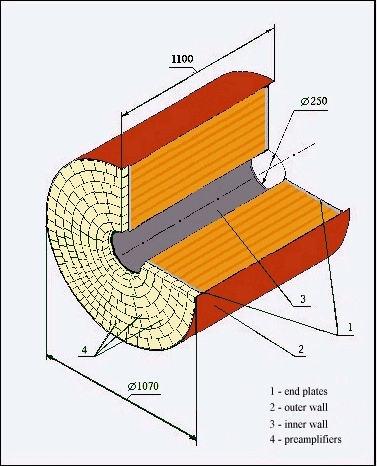
The drift chamber of the KEDR detector (Fig.1) has a cylindrical shape, its length equals 1100 mm, inner radius - 125 mm and outer radius - 525 mm. The drift cell, used in the drift chamber of the detector, is a slightly modified one, applied at first in the SLD detector.

The cell (Fig.2) contains eight anode wires, six of them are sensitive. The anode wires are spaced 4.5 mm apart in radial direction. There are two parallel rows of focusing wires in the distance of +- 3.5 mm at the left and right of the anode wires. The distribution of potential at the field wires provides an uniform field of 2.0 KV/cm in the drift gap. The field wires are placed approximately with a 4.5 mm step.

The anode, focus and edge field wire planes are rotated at 3o (the Lorentz angle for electrons, drifting in the cell at magnetic field of 1.8 T) with respect to the chamber radius, directed from the center of the chamber. The radial size of the cell equals 36 mm, the maximum drift distance is about 30 mm.

The chamber operates with pure dimethyl ether (DME) at atmospheric pressure. Use of DME in cells with the large drift distance, where the coordinate resolution is restricted by diffusion, gives possibility to obtain the cell average space resolution better than 100 micron.

The chamber wires are arranged in a system of seven concentric cylindrical super layers of cells described above (Fig.3). Four super layers have axial wires while the other three even-numbered super layers have wires inclined at angle +- 100 mrad with respect to the chamber axis. Stereo layers provide measurement of the particle coordinate along the DC axis.

Total number of anode wires in the chamber equals 1512. This gives 42 coordinate and ionization losses measurements for a particle crossing the chamber. The main parameters of the DC are given in the Table.

Table:Drift chamber parameters.
Inner radius: 125 mm
Outer radius: 535 mm
Length: 1100 mm
Length of wires: 970 mm
Number of axial super layers: 4
Number of stereo super layers: 3
Stereo angle: +-100 mrad
Number of coordinate measurements: 42
Number of cells: 252
Number of anode wires: 1512
Number of field and focusing wires: 11772
Number of shield wires: 2748
Total number of wires: 16032

Momentum resolution of drift chamber

Back to top

In magnetic field B the charged particle track curvature measurement gives the momentum P component transverse to magnetic field. For the total particle momentum determination one should measure also angle between vectors B and P.

To obtain a good resolution on momentum and angle of charged particles at fixed size of the DC and magnetic field strength (1.8 T) two parameters were used: the coordinate resolution and the quantity of matter in DC. To obtain a project coordinate resolution of 100 micron dimethyl ether was used, to increase radiation length of matter in DC the wires were produced of gilt titanium. The contribution to multiple scattering from gas and wires is about equal.

The calculated momentum resolution of DC in magnetic field of 1.8 T at 42 coordinate measurements with 100 micron accuracy and 370 mm base is:

(dPt/Pt)2= 0.0032+(0.0056P)2,

where P in (GeV/c). In the calculation of multiple scattering the matter of wires and operation gas was taken into account. To obtain contribution to momentum resolution of DC from multiple scattering the reconstructed trajectories were used with kink in the point were particle hits wire. This method of calculation diminishes contribution from scattering in 1.6 times.

When the momentum is measured by DC and vertex detector, the base increases up to 450 mm at 48 coordinate measurements. Momentum resolution in this case is equal to:

(dPt/Pt)2= 0.0032+(0.0033P)2,

P in GeV/c.

Solid angle for particles, crossing 3 super layers, equals 87 % and diminishes up to 70 % for 7 super layers. The accuracy of polar angle measurement depends on this angle. It becomes worse at angle larger than 45o.

Particle identification in drift chamber

Back to top

To study a possibility of particle separation in the DC of KEDR the usually used phenomenonlogical approach, suggested first by Valenta and based on experimental data, was applied. With this approach the calculation of particle separation in DC by ionization losses measurement can be quickly and quite accurately performed. Particle separation is measured in units of standard deviation.

Results of calculation of particles separation with the measurement of ionization losses for the KEDR DC is shown in Fig.4. At 42 measurements of ionization losses the resolution is 10.3 %, giving pi/K separation up to 600 MeV/c and K/p separation up to 1200 MeV/c at the 2 sigma level.

Electronics and high voltage supply

Back to top

At the electronics development the method of parallel read out of information was chosen, in which each anode wire is connected with the separate detection channel. The drift chamber electronics can be separated to chamber electronics and detection one.

The electronics placed at the chamber, this is the linear amplifier, developed and produced in Budker INP. The scheme of the chamber electronics is shown in Fig.5. The preamplifier is made on the base of microscheme K174UV5.

The detection electronics, placed in the control room, is based on the TAM plates for measurements of the drift time and the signal amplitude. The TAM plate can measure these parameters for four particles in one cell of DC. It process signals from six anode wires. Each channel commutates with four time and four amplitude detectors. The structure scheme of the TAM plate is shown in Fig.6. Signals from anode wires trough preamplifiers and communication line go to 6 differential receivers (elements 1-6) and then through commutator to time channels.

To organize the primary trigger there are 4 collectors of FOR signals (quick OR). These signals through trunk line of special crate go to the interface of the primary trigger (IPT). The FOR signals are formed in the entrance registers of the commutator.

For the secondary trigger organization the Yes-No information read out to the interface of the secondary trigger (IST) is foreseen in the plate. The Yes-No information is being collected in the entrance registers of the commutator during the electron drift time in the cell of DC.

The chamber is supplied from two high voltage sources of -2.85 KV and -8.6 KV, produced in the KAMAK standard. The high voltage from each source goes to the potentials distribution block (BD) Fig.7, where the voltage is separated to 21 independent channels. The DC is supplied from BD with 30 m long coaxial cables.

Back to top

Last update 9-Aug-2000